Frame1/B0XX layout style open-source digital controller software for the Raspberry Pi Pico (v0.8)
This is a modular, runtime-remappable and easily extensible digital controller software for the Raspberry Pi Pico, that can identify as various controllers and communicate over the Joybus (Gamecube/Wii) and USB protocols, with several digital to controller representation conversion modes built-in: Melee, P+, Ultimate, generic controller and generic keyboard.
Supported controller representations:
-
Gamecube controller (Joybus)
-
Gamecube controller to USB Adapter aka WUP-028 (USB, Switch compatible, compatible with WinUSB-only features)
-
Wired Fight Pad Pro (USB, Switch compatible)
-
8KRO Keyboard (USB)
All controller representations are plug-and-play, including the WUP-028 one, that will install WinUSB on plug-in.
Modes combining (GPIO -> Button sets) (Button sets -> Controller representation) (Controller representation -> USB Configuration/Joybus) configurations can be chosen at runtime initialization by pressing a given key when powering the controller.
This project doesn’t utilize TinyUSB, but instead implements the USB protocol itself to manage runtime-dependant descriptors. This is largely based on the dev_lowlevel pico-example project, although fully migrated to C++, with some extensions such as WCID compatibility and multi-packet control transfers.
LEGAL INFORMATION
THE SOFTWARE IS PROVIDED “AS IS”, WITHOUT WARRANTY OF ANY KIND, EXPRESS OR IMPLIED, INCLUDING BUT NOT LIMITED TO THE WARRANTIES OF MERCHANTABILITY, FITNESS FOR A PARTICULAR PURPOSE AND NONINFRINGEMENT. IN NO EVENT SHALL THE AUTHORS OR COPYRIGHT HOLDERS BE LIABLE FOR ANY CLAIM, DAMAGES OR OTHER LIABILITY, WHETHER IN AN ACTION OF CONTRACT, TORT OR OTHERWISE, ARISING FROM, OUT OF OR IN CONNECTION WITH THE SOFTWARE OR THE USE OR OTHER DEALINGS IN THE SOFTWARE.
In particular, when communicating over USB, device using this software may use the 0x057E USB Vendor ID, that is affiliated with Nintendo, and other proprietary USB vendor IDs. By uploading this software onto your board, you assert that you understand what that means and take entire responsability for it.
Safety information
Don’t have this board plugged via USB and via its Gamecube port at the same time. This would feed the USB 5v to the 3v line of the console and likely damage it.
If you want to prevent this electrically, use Schottky diodes, or power VSYS with the 5v from the console and don’t connect the console 3v. Be aware that doing this implies the controller won’t work on consoles with broken rumble lines anymore.
Perks of Raspberry Pico over atmega32u4 based controllers:
-
Up to 25 inputs + a console data line
-
No 5V input required (Voltage regulator accepts 3.3V)
-
No logic level shifter required (3.3V GPIO by default)
-
Extremely simple programming (USB drag and drop)
-
Much higher (~8x) MCU speed allows reacting to console poll rather than having to predict them, hence better latency (i.e matches Frame1 latency give or take a few cycles which is slightly better than that of B0XX/other atmega32u4 based controllers)
-
1000Hz effective reporting over USB, which some atmega32u4 based controllers (notably the B0XX) don’t have, granting better latency & latency stability
-
Identifying as a GCC to USB adapter where your controller is plugged in port 1 means that this is compatible with WinUSB-only features (Kristal’s netcode, timing dispersion reduction)
-
Very cheap ($4) and widely available
Modes
As of this release, 8 modes are built-in.
-
Not plugged into USB => Console mode (Melee F1 DAC algorithm + Joybus), unless you press GP2 or GP7 (by default Right and MY), in which case you enter P+ mode, or GP6 (by default MX), in which case you enter Ultimate mode. If you’re not plugged into USB, you enter this mode.
-
Plugged into USB, nothing pressed => Melee GCC to USB adapter mode (Melee F1 DAC algorithm + Adapter USB configuration).
-
GP16 (by default, CRight) => BOOTSEL mode. See “How to program your board”.
-
GP17 (by default, Up) => Runtime remapping. See dedicated paragraph.
-
GP7 (by default, MY) => P+ GCC to USB adapter mode (P+ DAC algorithm + Adapter USB configuration).
-
GP2 (by default, Right) => Wired Fight Pad Pro with P+ logic (P+ DAC algorithm + Wired Fight Pad Pro USB configuration).
-
GP6 (by default, MX) => Ultimate GCC to USB adapter mode (Ultimate DAC algorithm + Adapter USB configuration).
-
GP5 (by default, L) => Wired Fight Pad Pro with Melee logic (Melee F1 DAC algorithm + Wired Fight Pad Pro USB configuration).
-
GP4 (by default, Left) => Wired Fight Pad Pro with dedicated logic (Wired Fight Pad Pro DAC algorithm + Wired Fight Pad Pro USB configuration). See lower for DAC algorithm explanation.
-
GP0 (by default, Start) => 8KRO Keyboard (8 Keys set DAC algorithm + 8KRO Keyboard USB configuration). See lower for mapping.
Software architecture
The code is split in 4 parts.
-
GPIO to button sets: define pinouts. By default only one is defined, the one advised lower in this README. Change it directly if you use a different pinout for whatever reason, change it. (If you don’t plan on making other changes, using the default allows you to use the .uf2 directly instead of recompiling on every update) If, say, you want to have the same controller logic (SOCD handling, etc.) for 2 characters but have a different button mapping, make 2 profiles there.
-
DAC algorithms aka, from button sets to a controller representation. Controller representation being, as of this release, a Gamecube controller, a Wired Fight Pad Pro or an 8KRO keyboard. This is where the digital to analog and in fact, digital to anything logic, happens. This is where the PM/P+/Ultimate logic will be when I get to them.
-
USB configurations: this is where the structure that the DAC algorithms must fill is exposed, and where the logic specific to identifying as a given USB peripheral happens. As of this release, this includes a WUP-028 adapter, a Wired Fight Pad Pro and an 8KRO Keyboard.
-
Communication protocols: This is the protocol specific code. You most likely don’t need to touch these.
Melee mode notes
The logic is that of the Frame1, with the slight side B and parasol dashing nerfs removed. They can be added back in the code via a toggle.
Wired Fight Pad Pro mode logic
With the Melee F1 DAC algorithm, Start is mapped to Home. L, R and Z are respectively mapped to ZL, ZR and R. -, +, L and Photo are inaccessible. The purpose of this mode is to allow playing on a PC setup with other people that are using vanilla Gamecube controllers through an adapter, as Slippi can’t handle multiple adapters at once. There may be slight analog discrepancies occuring as a result of using the Standard Controller mode (max 1 tick).
In dedicated mode, Modifiers and LS/MS are repurposed. This means you can only access cardinals and diagonals on the control stick.
- LS => L
- Z => R
- L => ZL
- R => ZR
- MX => -
- MY => +
- Start => Home
- MS and Left => Dpad left
- MS and Right => Dpad right
- MS and Up => Dpad up
- MS and Down => Dpad down
- MS and Start => Photo
8KRO Keyboard mappings
Button mappings:
- L => q
- Left => w
- Down => e
- Right => r
- MX => a
- MY => s
- Start => t
- R => y
- B => h
- Y => u
- X => j
- LS => i
- Z => k
- MS => o
- Up => l
- C-Up => g
- C-Left => f
- C-Right => b
- C-Down => c
- A => v
Adapter mode information
In adapter mode, upon connecting the Raspberry Pi Pico to your PC after uploading the software at hand onto it, the Raspberry Pi Pico will identify as a “WUP-028” i.e a Gamecube controller to USB adapter. Things will behave as if the Gamecube controller this board emulates was plugged in port 1. You need to use the “GameCube Adapter for Wii U” in the Slippi Controllers tab (which is the default). You don’t need to configure anything.
However, in order to use this controller, you must first unplug any Gamecube controller to USB adapter connected to your PC, as softwares will typically only support communicating with one adapter at a time (notably Dolphin/Slippi).
Note that this mode of operation requires the “WinUSB” driver to be associated with this device. If you’ve used a Gamecube controller to USB adapter before, chances are you’ve associated WinUSB to the WUP-028 through Zadig. But even if you haven’t, you shouldn’t need to, as WinUSB will be installed automatically upon plugging the Pico board in.
Note that polling rate enforcements using the HIDUSBF filter driver that apply to “standard” WUP-028s will apply to this board, so enforced rates less than 1000Hz you could have configured would decrease this controller’s performance, which is 1000Hz by default.
Automated WinUSB installation is very experimental. If you encounter any driver related issue, please contact me.
Runtime remapping information
This project allows you to modify the default pin -> button mappings (i.e that of GpioToButtonSets::F1) in a persistent manner at runtime, i.e you don’t need to download any development tools, modify the code and reprogram the board, follow these instructions once and your mappings will be changed forever and will persist even when you update the firmware.
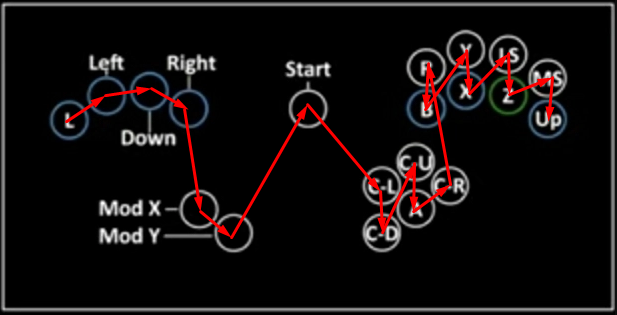
When plugging the board, press whichever button is mapped to GP17 (in the default pinout, it’s Up). 3 seconds later, you’ll enter remapping mode. Press the buttons in the following order: L Left Down Right MX MY Start CLeft CDown CUp A CRight R B Y X LS Z MS Up.
Note that you must release GP17 before the 3 seconds expire, or it will be considered as the first button press (L).
So, if for example you haven’t followed the default pinout when soldering and would like to go back to the default B0XX/F1, you’ll press the buttons in this order:
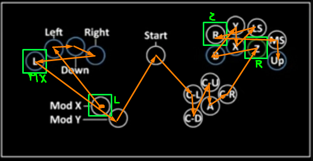
Say you’d like to swap L/MX, and R/Z, you’d press the buttons in this order:
When plugging the board in, wait for 3+ seconds before starting to press any buttons.
The remapping will be committed when you’ve pressed 20 different buttons. You must restart (i.e unplug/replug) to enter another mode. The pins you can map something to are GP 0-22 and GP 26-27, i.e all accessible pins EXCEPT GP28, that is dedicated to the GC Data pin.
If it doesn’t appear to work, double check all 20 of your buttons work. Note that runtime remapping doesn’t change what buttons you need to press to enter a given mode, as it is the pin number that matters.
How to program your board:
-
Download the latest release (on the right of the Github page)
-
Plug in your Raspberry Pico to your computer by holding pin GP26 (the CRight button in the advised pinout) via USB (i.e BOOTSEL mode), or while holding the “BOOTSEL” white button on the board.
-
The board should appear as an external drive. Put the .uf2 in there. The board should disconnect and be ready for use.
If you reconnect the board in BOOTSEL mode, you won’t see the .uf2 file anymore. This is normal, expected behavior.
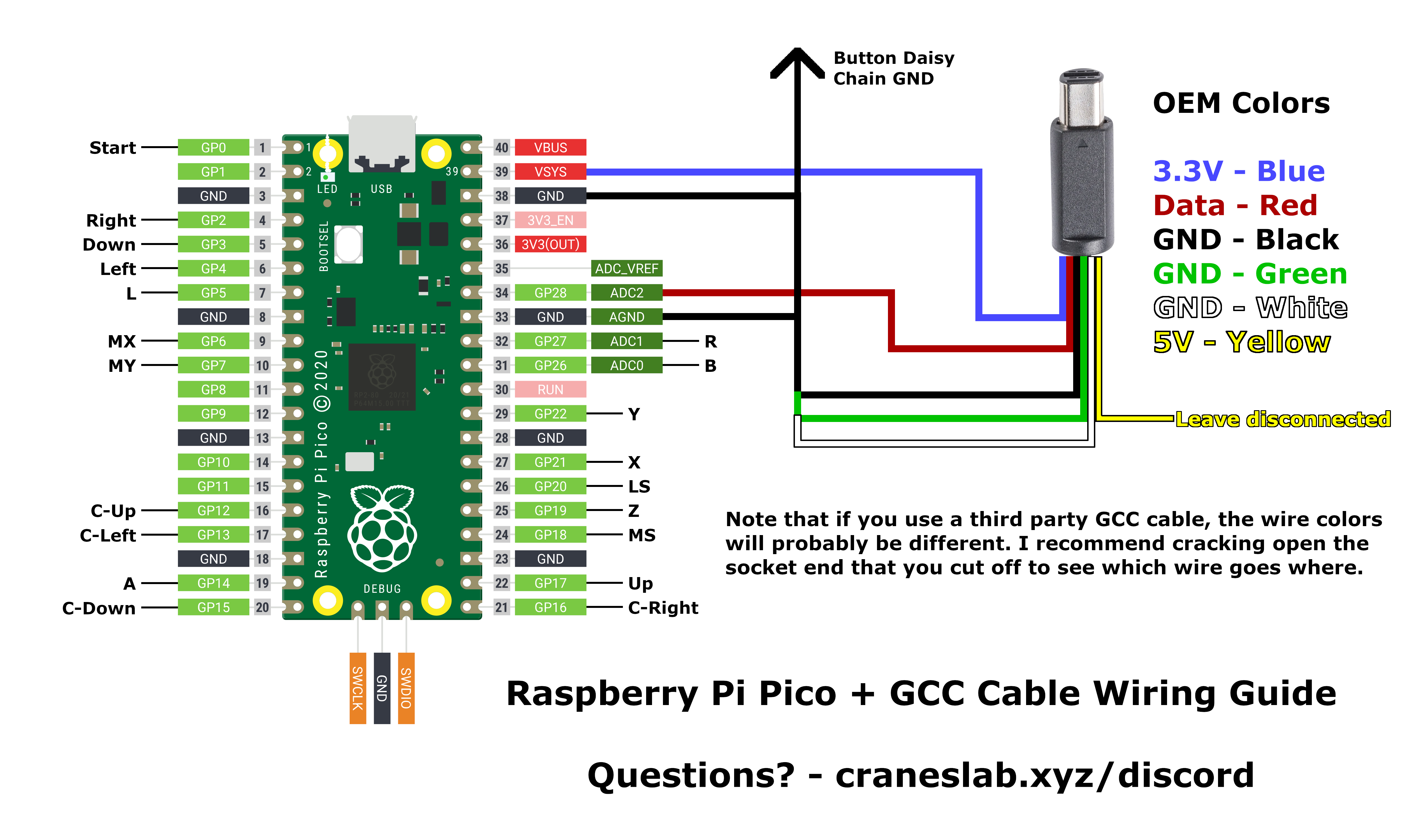
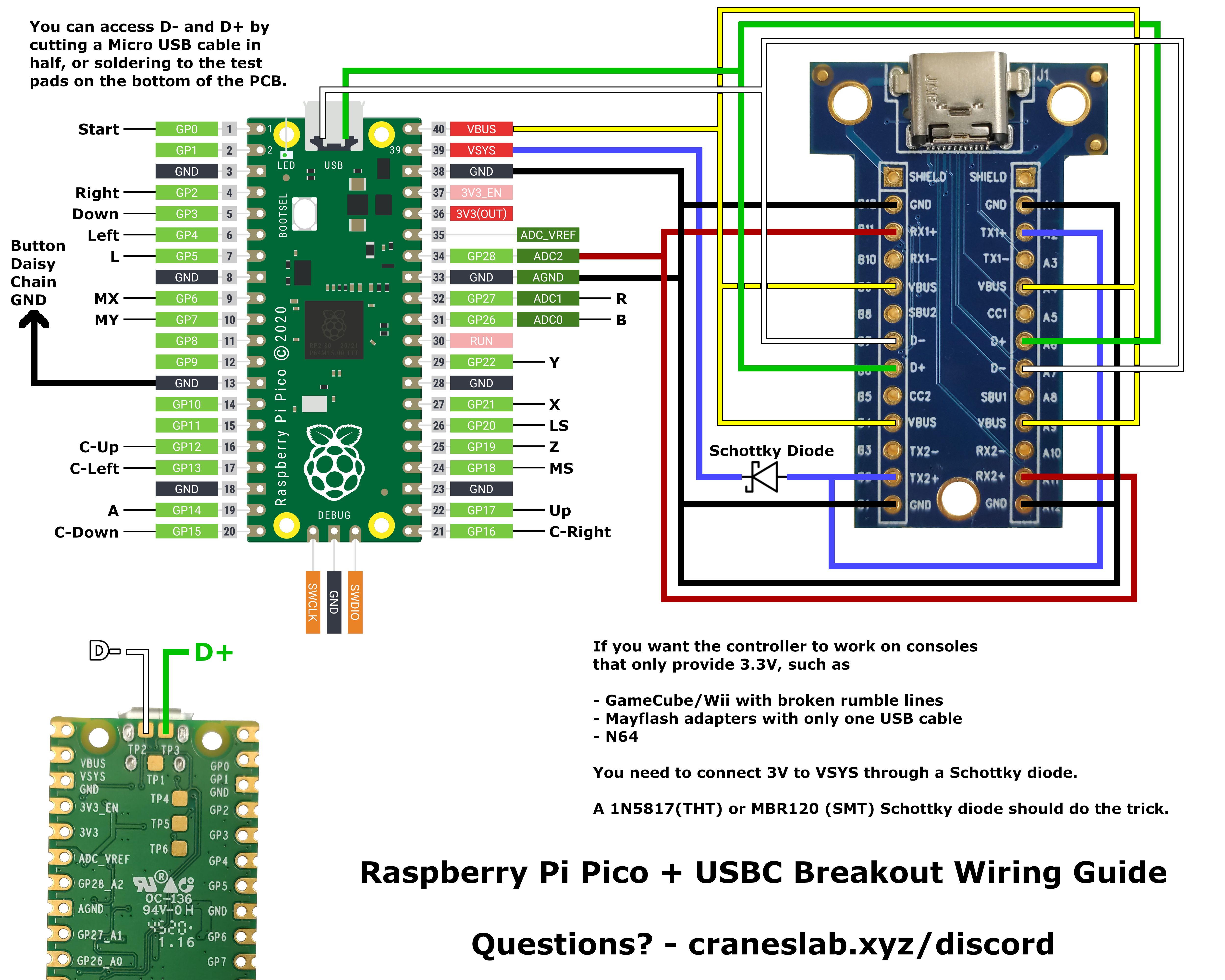
How to wire the board:
If you just have a GameCube cable :
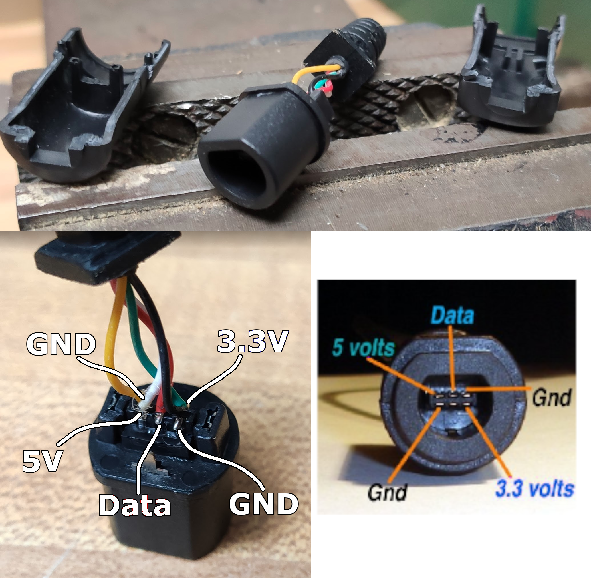
If you are using a third party cable :
If you are using a generic USB-C breakout :
If you are using a Model U breakout :
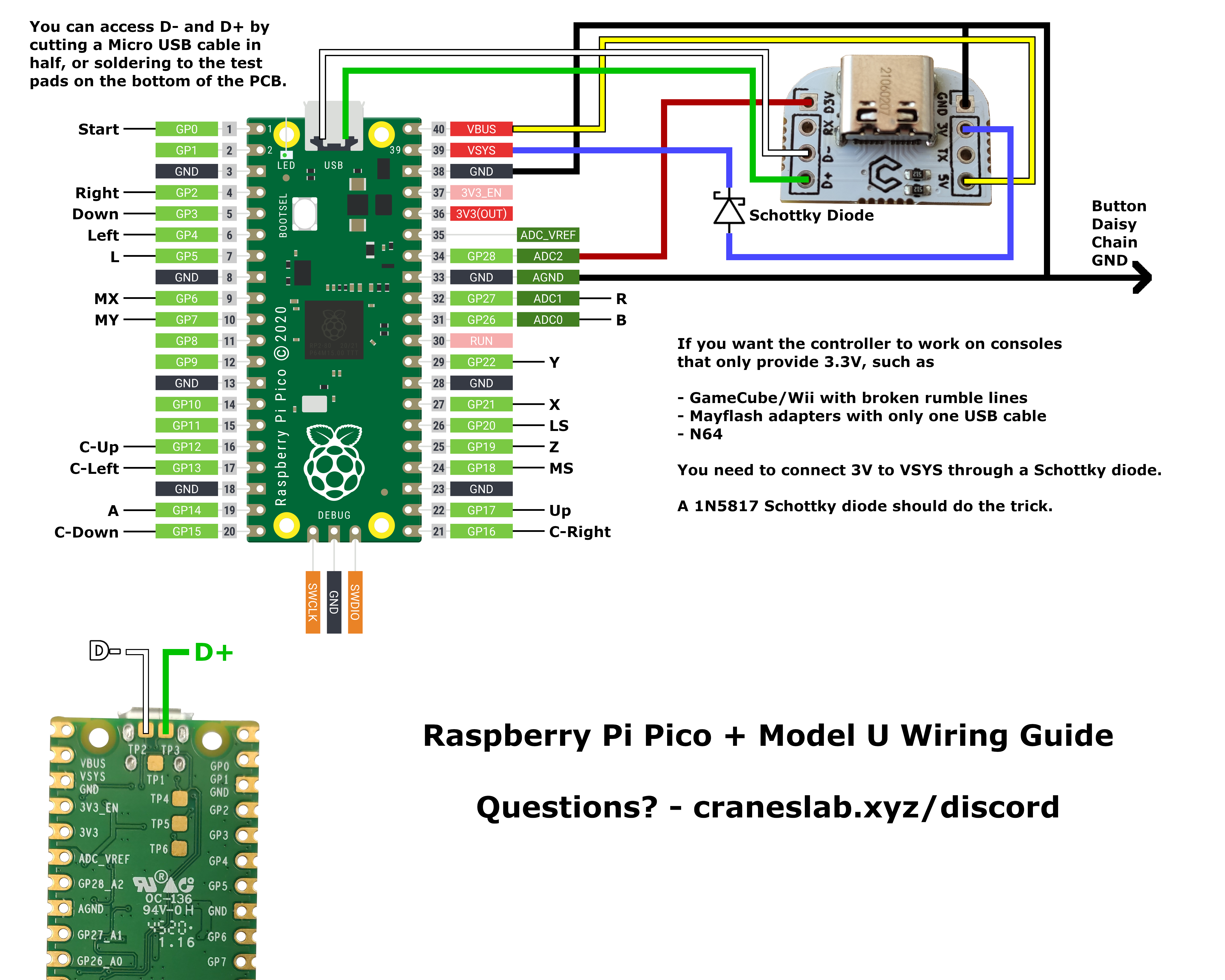
Switches/buttons will have two pins. Connect one of them to Ground (daisy chaining advised) and the other to a Pico GPIO pin following the mapping shown in the images above.
Note that all “button” pin mappings can be modified later on using the runtime remapping feature, but the GameCube Data line can’t and must be connected to GP28.
Troubleshooting
Console mode/B/R don’t work -> Did you connect pin 33 to ground ?
Nothing but B/R works -> Did you connect pin 38 to ground ?
Only half/some of my buttons do anything -> Double-check your common ground between all of your buttons.
Closing notes
I intend to add P+/PM support shortly. The v1.0 release will happen after that. Until then, the project is in beta and default configurations (mode pins, keyboard mappings, wired fight pad pro mappings) may change. Before I can do the full release, everything has to be tested thoroughly, so any help with testing is appreciated. Especially the Ultimate mode !
Contact
Discord: Arte#9281
Twitter: https://twitter.com/SSBM_Arte
Open this page at https://ericl810.github.io/pico-rectangle-l810/
Use as Extension
This repository can be added as an extension in MakeCode.
- open https://maker.makecode.com/
- click on New Project
- click on Extensions under the gearwheel menu
- search for https://github.com/ericl810/pico-rectangle-l810 and import
Edit this project 
To edit this repository in MakeCode.
- open https://maker.makecode.com/
- click on Import then click on Import URL
- paste https://github.com/ericl810/pico-rectangle-l810 and click import
Blocks preview
This image shows the blocks code from the last commit in master. This image may take a few minutes to refresh.

Metadata (used for search, rendering)
- for PXT/maker